This page describes common methods for measuring input and output latency.
There are several techniques available to measure output latency, with varying degrees of accuracy and ease of running, described below. Also see the Testing circuit for an example test environment.
This test measures latency in relation to the device's LED indicator. If your production device does not have an LED, you can install the LED on a prototype form factor device. For even better accuracy on prototype devices with exposed circuity, connect one oscilloscope probe to the LED directly to bypass the light sensor latency.
If you cannot install an LED on either your production or prototype device, try the following workarounds:
To conduct this test:
Note: To get useful results, it is crucial to use the correct APIs in the test app so that you're exercising the fast audio output path. See Design For Reduced Latency for background.
The difference in time is the approximate audio output latency, assuming that the LED latency and light sensor latency are both zero. Typically, the LED and light sensor each have a relatively low latency on the order of one millisecond or less, which is sufficiently low enough to ignore.
Round-trip latency is the sum of output latency and input latency.
One of the easiest latency tests is an audio feedback (Larsen effect) test. This provides a crude measure of combined output and input latency by timing an impulse response loop. This test is not very useful for detailed analysis by itself because of the nature of the test, but it can be useful for calibrating other tests, and for establishing an upper bound.
To conduct this test:
This method does not break down the component times, which is important when the output latency and input latency are independent. So this method is not recommended for measuring precise output latency or input latency values in isolation, but might be useful for establishing rough estimates.
Output latency to on-device speaker can be significantly larger than output latency to headset connector. This is due to speaker correction and protection.
We have published an example implementation at
slesTestFeedback.cpp.
This is a command-line app and is built using the platform build environment;
however it should be straightforward to adopt the code for other environments.
You will also need the non-blocking FIFO code
located in the audio_utils library.
The Dr. Rick O'Rang audio loopback dongle is handy for measuring round-trip latency over the headset connector. The image below demonstrates the result of injecting an impulse into the loop once, and then allowing the feedback loop to oscillate. The period of the oscillations is the round-trip latency. The specific device, software release, and test conditions are not specified here. The results shown should not be extrapolated.
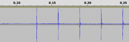
Figure 1. Round-trip measurement
You may need to remove the USB cable to reduce noise, and adjust the volume level to get a stable oscillation.
Input latency is more difficult to measure than output latency. The following tests might help.
One approach is to first determine the output latency using the LED and oscilloscope method and then use the audio feedback (Larsen) test to determine the sum of output latency and input latency. The difference between these two measurements is the input latency.
Another technique is to use a GPIO pin on a prototype device. Externally, pulse a GPIO input at the same time that you present an audio signal to the device. Run an app that compares the difference in arrival times of the GPIO signal and audio data.
To achieve low audio latency, pay special attention throughout the
system to scheduling, interrupt handling, power management, and device
driver design. Your goal is to prevent any part of the platform from
blocking a SCHED_FIFO audio thread for more than a couple
of milliseconds. By adopting such a systematic approach, you can reduce
audio latency and get the side benefit of more predictable performance
overall.
Audio underruns, when they do occur, are often detectable only under certain conditions or only at the transitions. Try stressing the system by launching new apps and scrolling quickly through various displays. But be aware that some test conditions are so stressful as to be beyond the design goals. For example, taking a bugreport puts such enormous load on the system that it may be acceptable to have an underrun in that case.
When testing for underruns:
Once you find the underlying causes of underruns, reduce the buffer counts and sizes to take advantage of this. The eager approach of reducing buffer counts and sizes before analyzing underruns and fixing the causes of underruns only results in frustration.
systrace is an excellent general-purpose tool
for diagnosing system-level performance glitches.
The output of dumpsys media.audio_flinger also contains a
useful section called "simple moving statistics." This has a summary
of the variability of elapsed times for each audio mix and I/O cycle.
Ideally, all the time measurements should be about equal to the mean or
nominal cycle time. If you see a very low minimum or high maximum, this is an
indication of a problem, likely a high scheduling latency or interrupt
disable time. The tail part of the output is especially helpful,
as it highlights the variability beyond +/- 3 standard deviations.