ITS-in-a-box consists of a plastic box that is laser cut from computer-aided
design (CAD) drawings, a chart tablet, and a device under test (DUT). This page
provides step-by-step instructions for assembling the ITS-in-a-box.
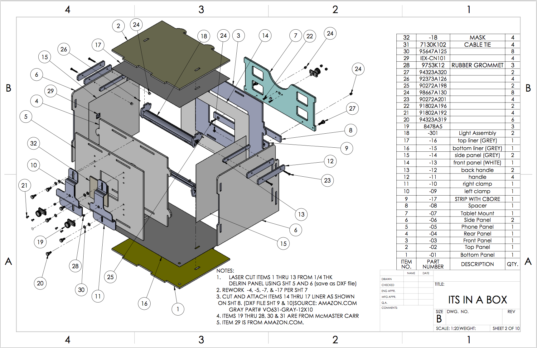
Figure 1. CAD image for ITS-in-a-box.
Required tools
Before getting started, ensure you have
downloaded the technical
drawings for the ITS-in-a box and have the following tools available:
- Phillips head screwdriver
- Pliers
- Exacto knife
- Wire cutters or scissors (optional)
Step 1: Lighting
To assemble the ITS-in-a-box lighting component:
- Gather the lighting hardware shown in Figure 2:
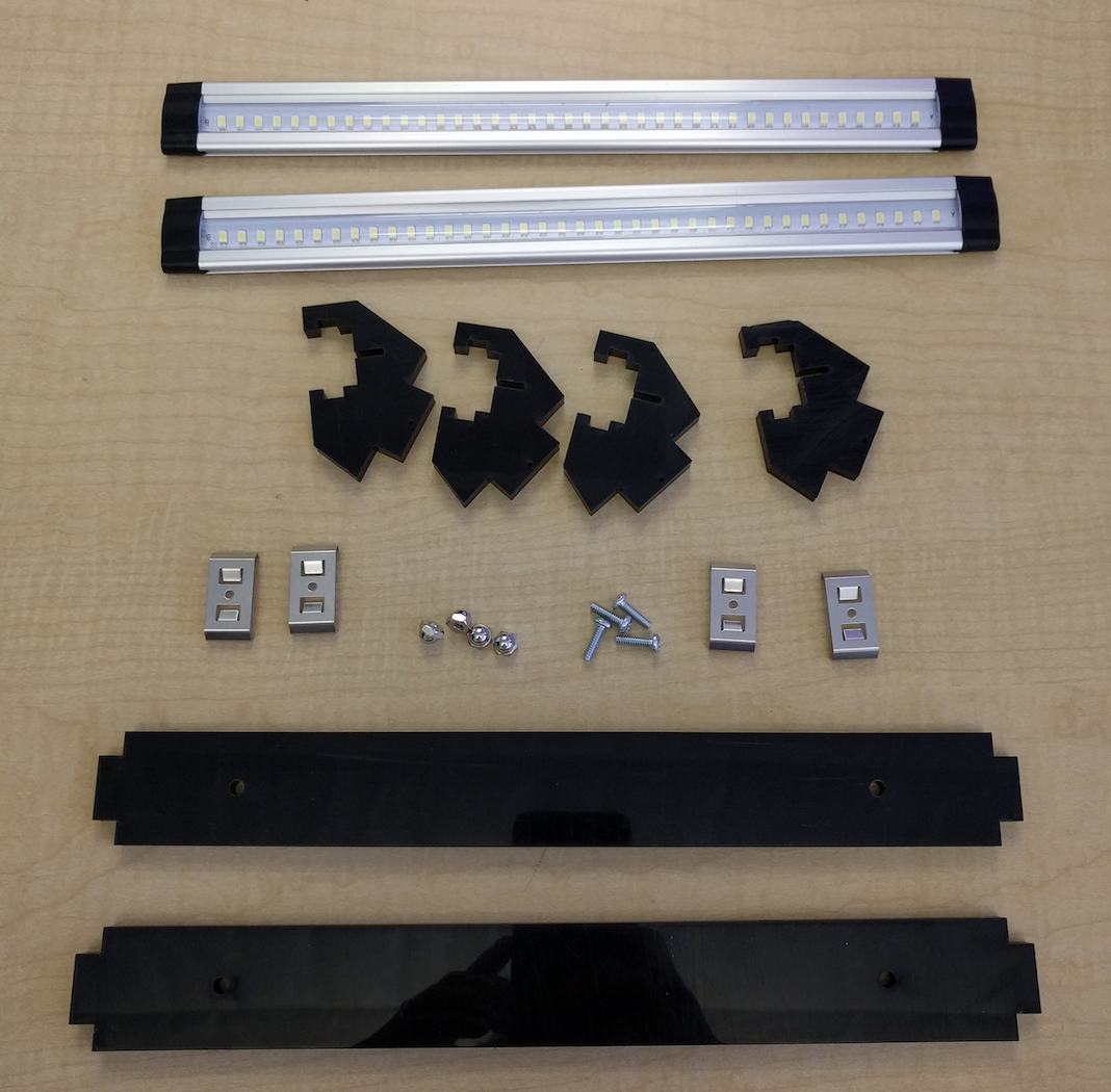
Figure 2. Light assembly parts.
Hardware includes LED light bars, plastic light baffles, plastic light mounts,
metal light clips included in the LED lighting kit, and four 6-32 screws with
acorn head nuts.
- Place LED light bars in the mounts with lights pointing down and towards
the table, as shown in Figure 3 (left side):
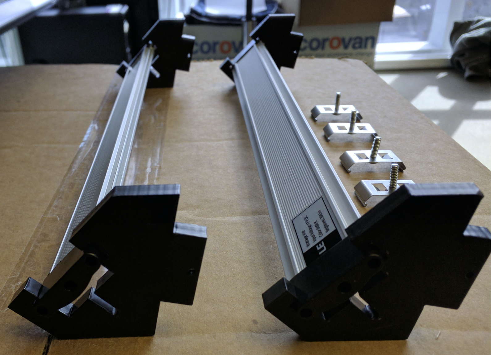
Figure 3. Close-up of light bars with lights facing down
and screws threaded through clips.
Thread the screws through the light clips using a screwdriver and while holding
the metal clip. The screw head should be be on the inside of the C shape of the
light clip as shown in Figure 3 (right side). Threading the screws requires
pressure as the fit is tight.
- Bolt the clips to the plastic baffles as shown in Figure 4:
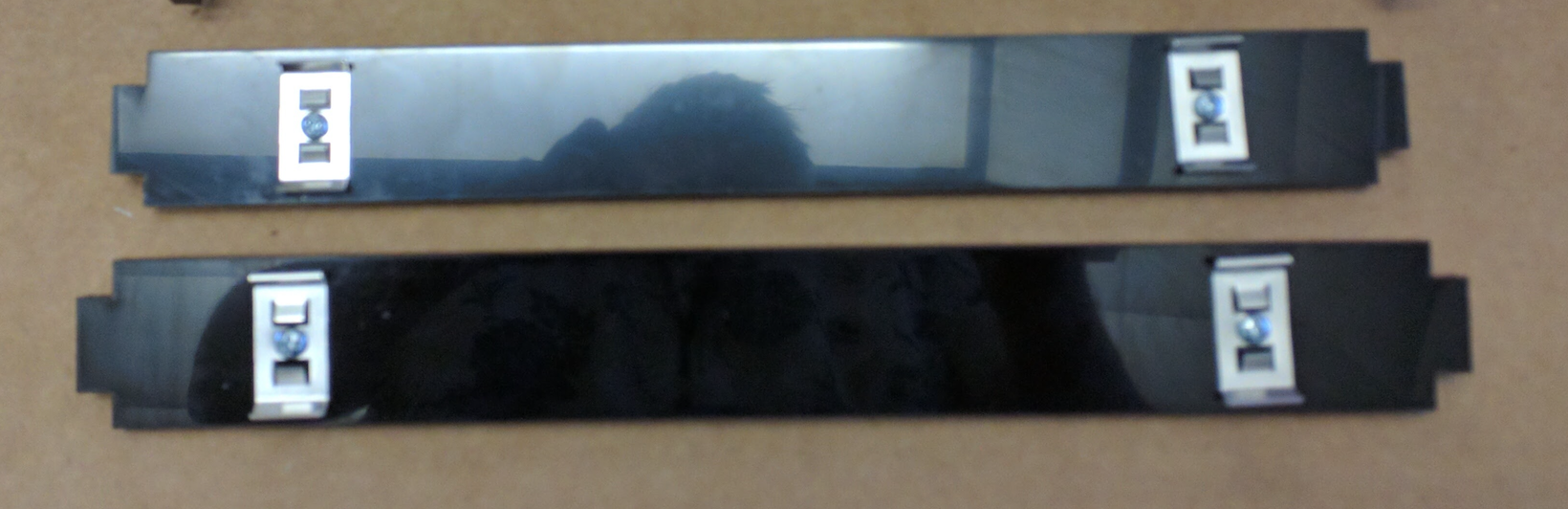
Figure 4. Light baffles with clips attached (acorn nuts are on
the side of the plastic not shown).
- Assemble the lights by snapping the baffles to the LED light backs with the
clips.
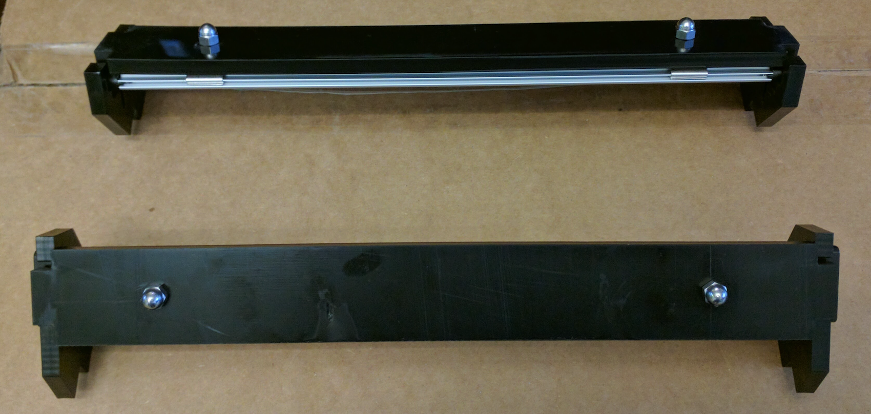
Figure 5. Assembled lights.
The LED lights should point down and the plastic should form a back to the light
to block the shiny, reflective back of the LED light bar.
Step 2: Phone mounts
To assemble phone mounts:
- Gather the phone mount hardware shown in Figure 6:
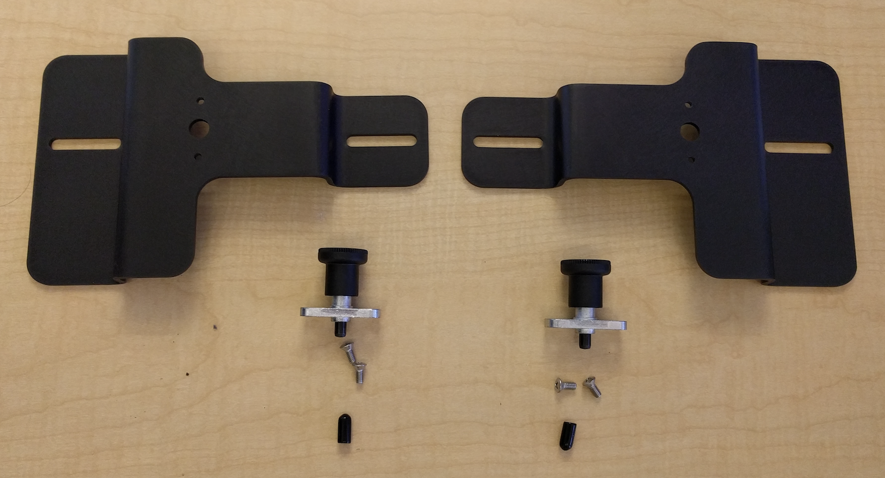
Figure 6. Phone mount assembly parts.
Hardware includes two aluminum phone trays, two plungers, two rubber tips, and
four 8-32 pan-head screws.
- Cut the rubber tips short enough to not interfere with plunger operation
(roughly in half), then use the rubber tips to cover the plungers.
- Assemble the phone mounts using pan-head screws to attach the plunger
mechanisms to the aluminum trays.
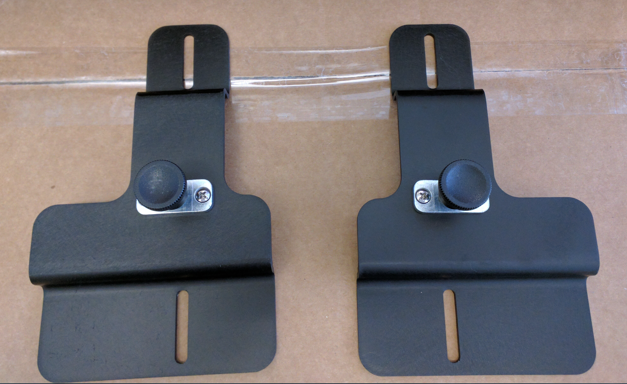
Figure 7. Assembled phone mounts.
Ensure the screws do not protrude beyond the plunger in the retracted or
extended plunger position.
Step 3: Aperture plate
To assemble the front aperture plate:
- Gather the front aperture plate hardware shown in Figure 8:

Figure 8. Front aperture plate assembly parts (front plate
top has the narrower space from slots for tabs to edge).
Hardware includes four short nylon screws (provided in the ITS-in-a-box kit) and
eight washers (required to keep the screws from protruding through the back of
the plastic plate).
- Add phone mounts to the front square aperture plate as shown in Figure 9:
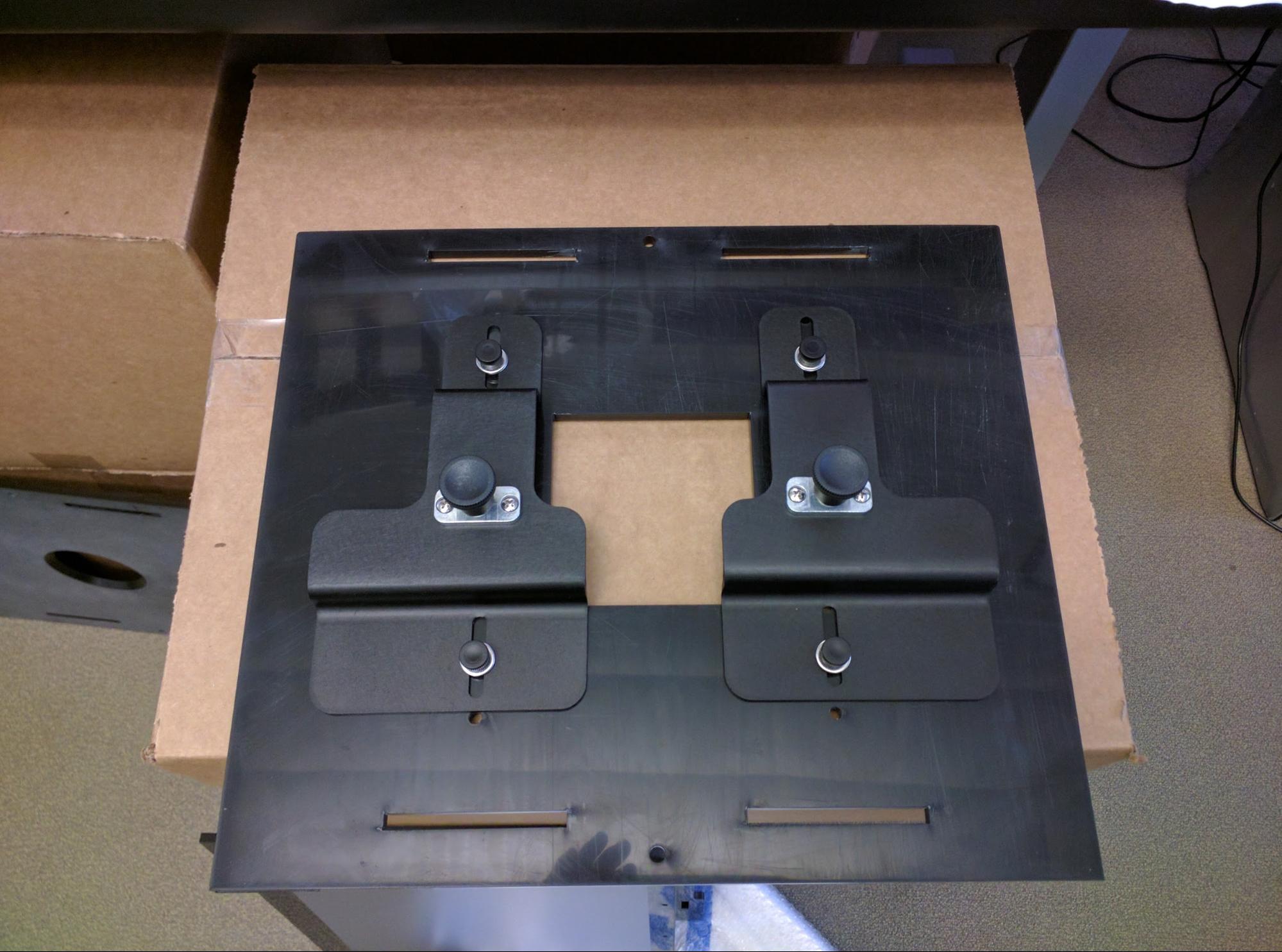
Figure 9. Assembled front plate, phone mounts in middle
position.
Step 4: Tablet holder
To assemble the tablet holder:
- Gather the tablet holder parts shown in Figure 10:
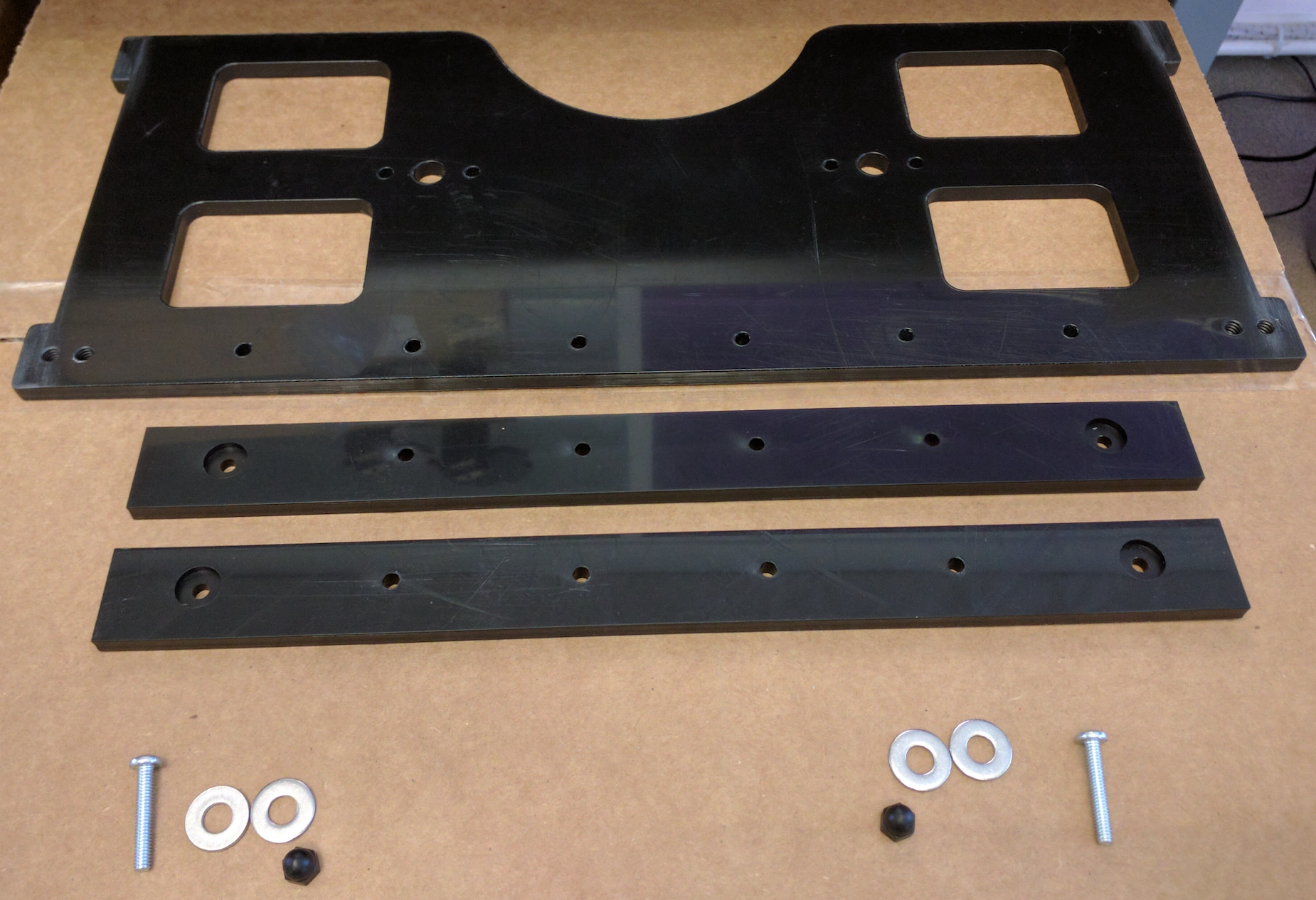
Figure 10. Tablet holder space assembly parts.
- Attach the spacer bars to the back of the tablet holder by threading a
nylon screw into the hole at the bottom-left or bottom-right of the tablet
holder (the screw threads properly in only one direction).
- Mount the spacers on the opposite side of the nylon screw as shown in Figure
11:

Figure 11. Tablet holder, location of plastic spacers and
nylon screw.
- Assemble the tablet holder with the screw head in the counter-drilled
plastic, then assemble the remaining pieces as shown in Figure 12.
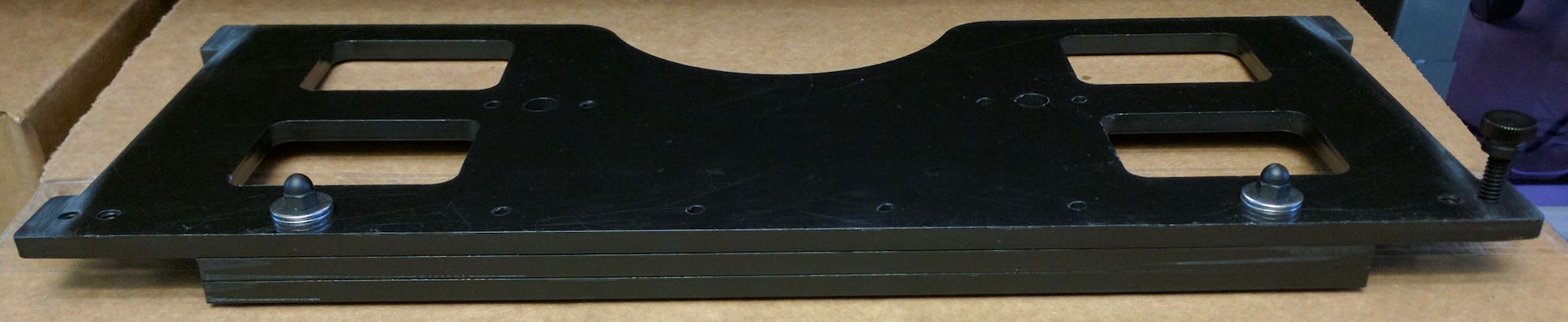
Figure 12. Assembled tablet holder spacer (washers account for
thickness variations in the plastic).
- Gather the tablet plunger parts as shown in Figure 13:
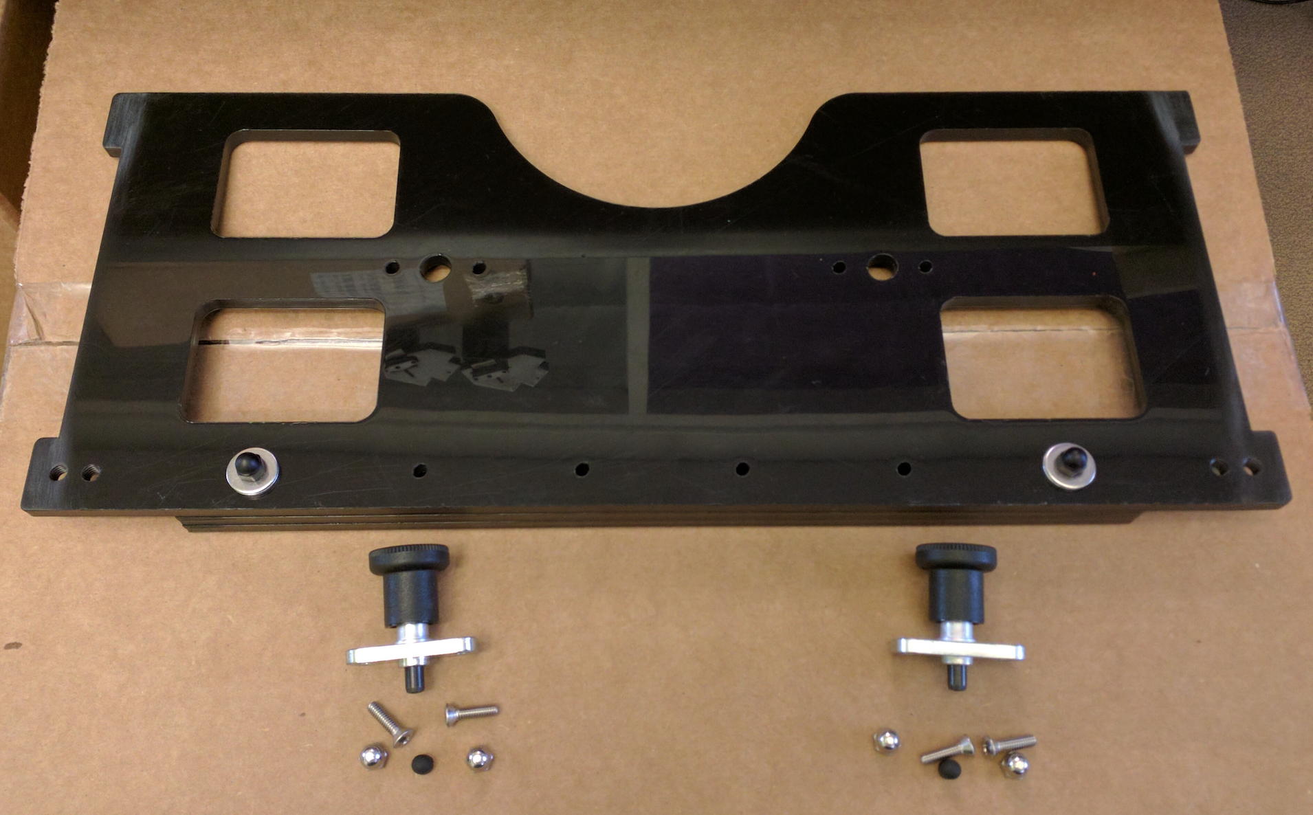
Figure 13. Tablet plunger parts with plastic tips cut
(later designs have only one plunger in the center).
- Cut the plastic tips to correct length and use the tips to cover the
plunger heads.
- Attach plungers to the plastic, placing the acorn nuts on the outside to
ensure minimum clearance on the inside for the tablet (and to prevent
interference with plunger operation.
- Connect the plunger(s) with the screw heads facing the box as shown in
Figure 14:
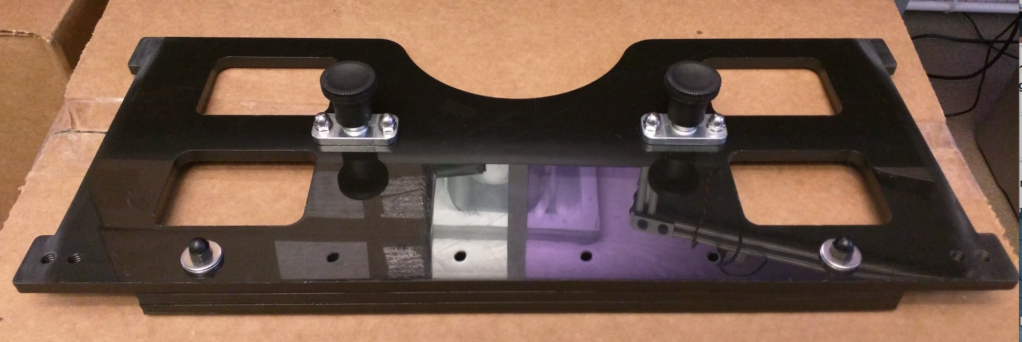
Figure 14. Assembled tablet holder (acorn nuts face away
from back panel of box).
All acorn nuts are on the same side of the tablet holder to maximize clearance
for the tablet.
Step 5: Assemble box
To assemble the box:
- Place the front panel with the circular aperture flat on the table, inside
facing up.
- Connect the front and back walls by inserting tabs into slots as shown in
Figure 15:
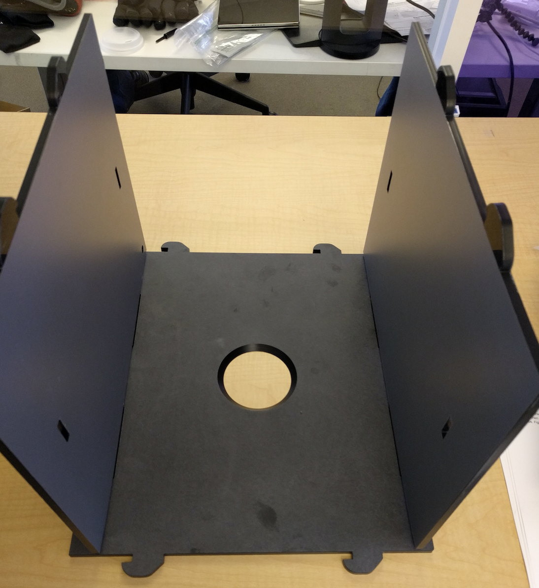
Figure 15. Top and bottom attached to front (as seen from
right side).
Position the front so the chamfered side of the circular aperture is on the
inside of the box. The front of the bottom can be identified by the small hole
for the power cord box exit (out of the field of view). The plastic hooks for
the sides should be pointed in the same direction.
- Attach the back to the top and bottom as shown in Figure 16:
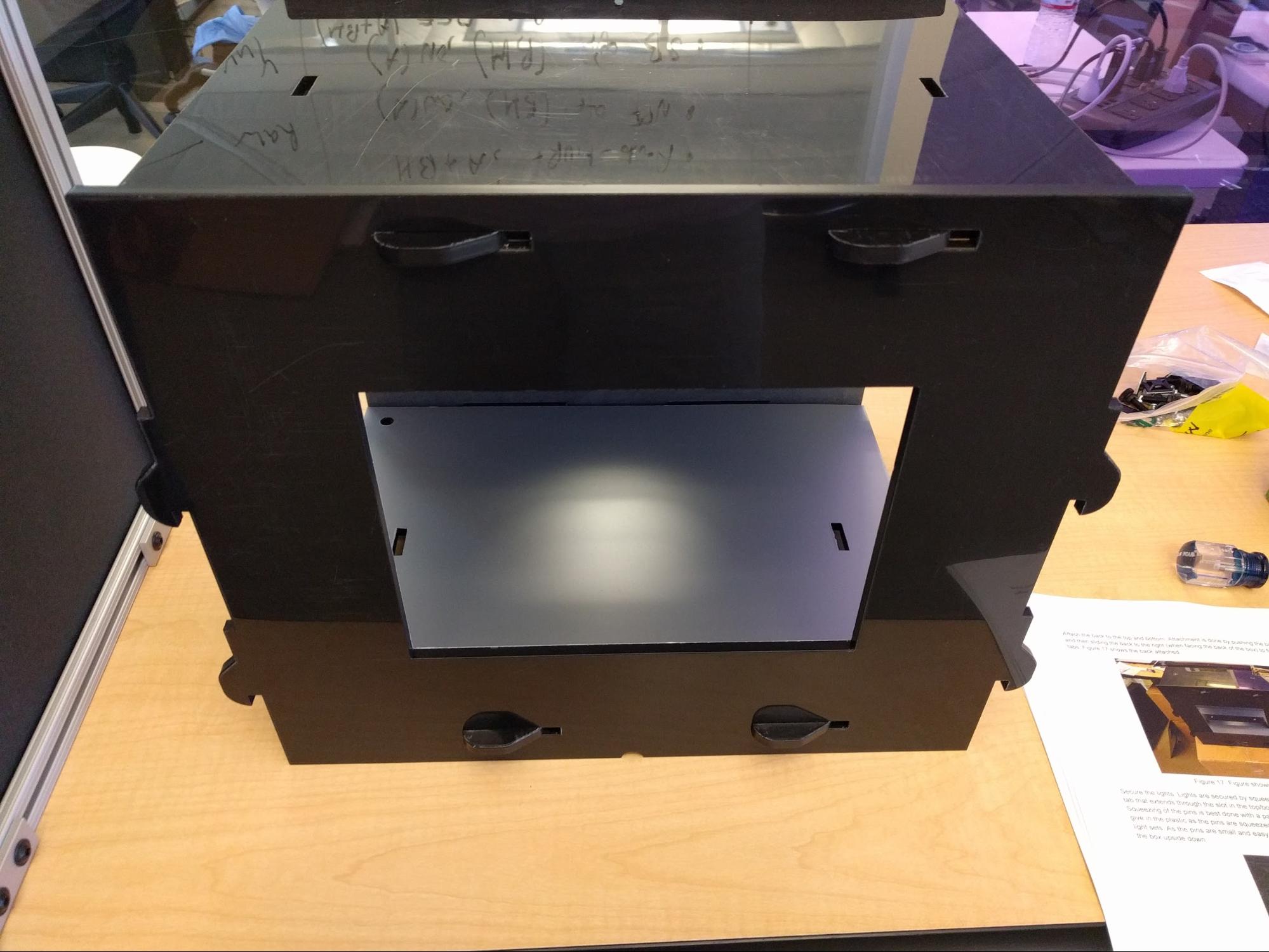
Figure 16. Back attached, no sides.
Push the back onto the tabs, then slide the back to the right (when facing the
back of the box) to fit under the hooked tabs.
Step 6: Install lights
To install the lights:
- Place lights in the assembled box as shown in Figure 17:
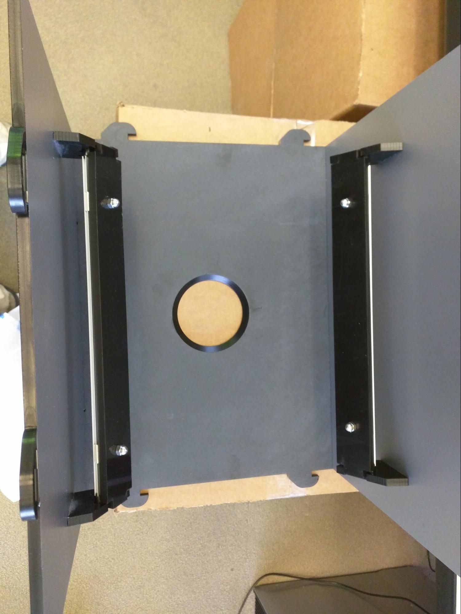
Figure 17. Proper light placement (back removed).
Ensure lights are pointed in the right direction (towards the top and bottom and
towards the front of the box).
- Secure lights by squeezing the pin into the small hole on the rectangular
tab that extends through the slot in the top/bottom, as shown in Figure 18:
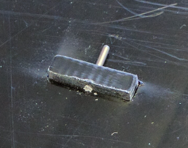
Figure 18. Detail of inserted pin in LED mount tab on outside
of box.
Squeezing of the pins is best done with a pair of pliers using gentle pressure;
you should feel a little give in the plastic as the pins are squeezed in place.
Insert the pins for both the bottom and top light sets. As the pins are small
and easy to drop, it is easiest to insert them to the bottom with the box
upside down.
- Attach the power cord to the lower light bar as shown in Figure 19:
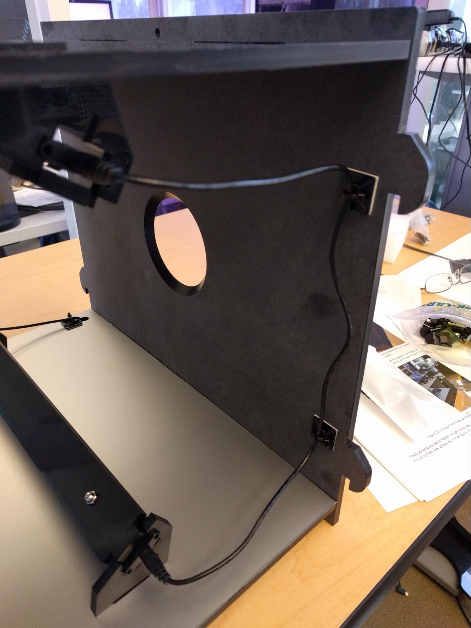
Figure 19. Detail of lighting power cord.
Thread the power cord through the hole in lower-front-right. The power cord has
different connectors at each end: The narrow connector fits to the LED light bar
and the larger connector fits to the power adaptor.
- To prevent the power cord from pulling on the light assembly, use a zip tie
to secure the power cord to bottom of box as shown in Figure 20:

Figure 20. Power cord zip tie attachment on bottom of box
(shown on its side); trim ties as necessary.
- Wire the top lights to the bottom lights on the left side and secure the
cable to the front of the box. Some drawings show the cable secured on side of
box, but it is easier to wire them to front corner as shown in Figure 21:
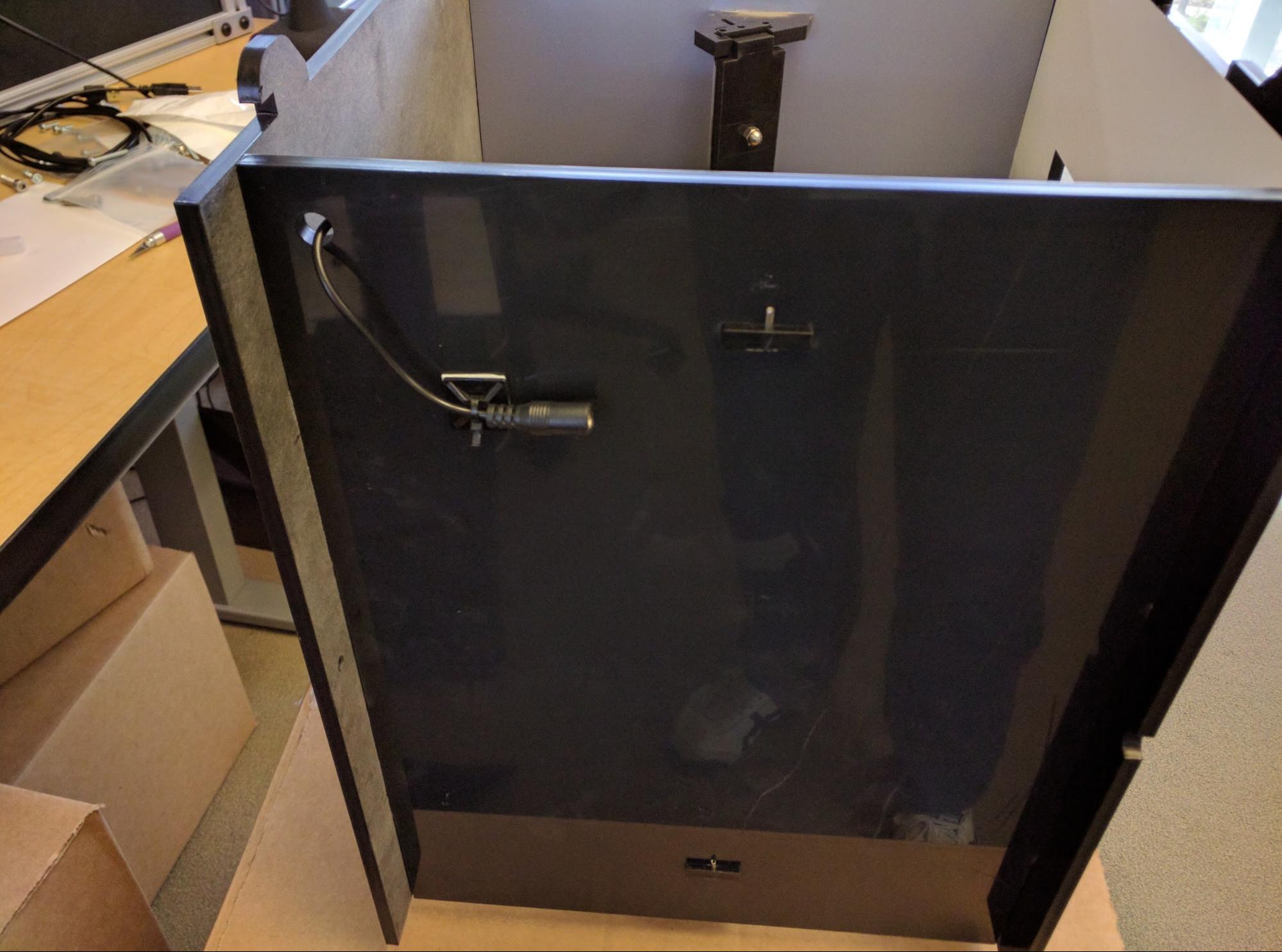
Figure 21. Detail of light cord anchored out of field of
view.
Step 7: Attach sides, tablet holder, and handles
To attach the box sides, tablet holder, and handles with locking mechanism:
- Snap the right panel into place by pushing and sliding it upwards. The
bottom of the panel should be flush with the bottom of the front and back panels
as shown in Figure 22:
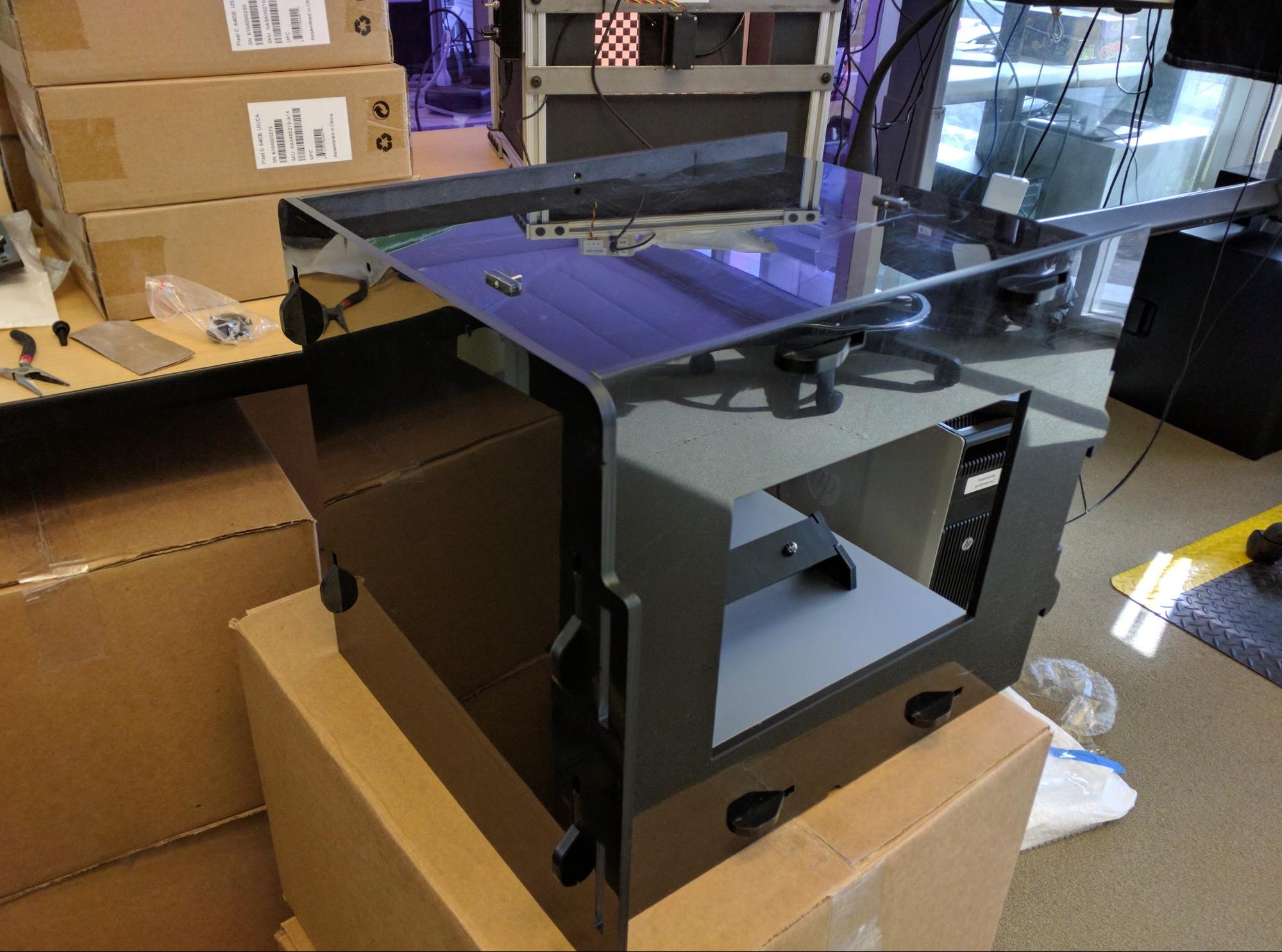
Figure 22. Right side panel in place (viewed from back).
- Place assembled tablet holder in right tabs as shown in Figure 23:
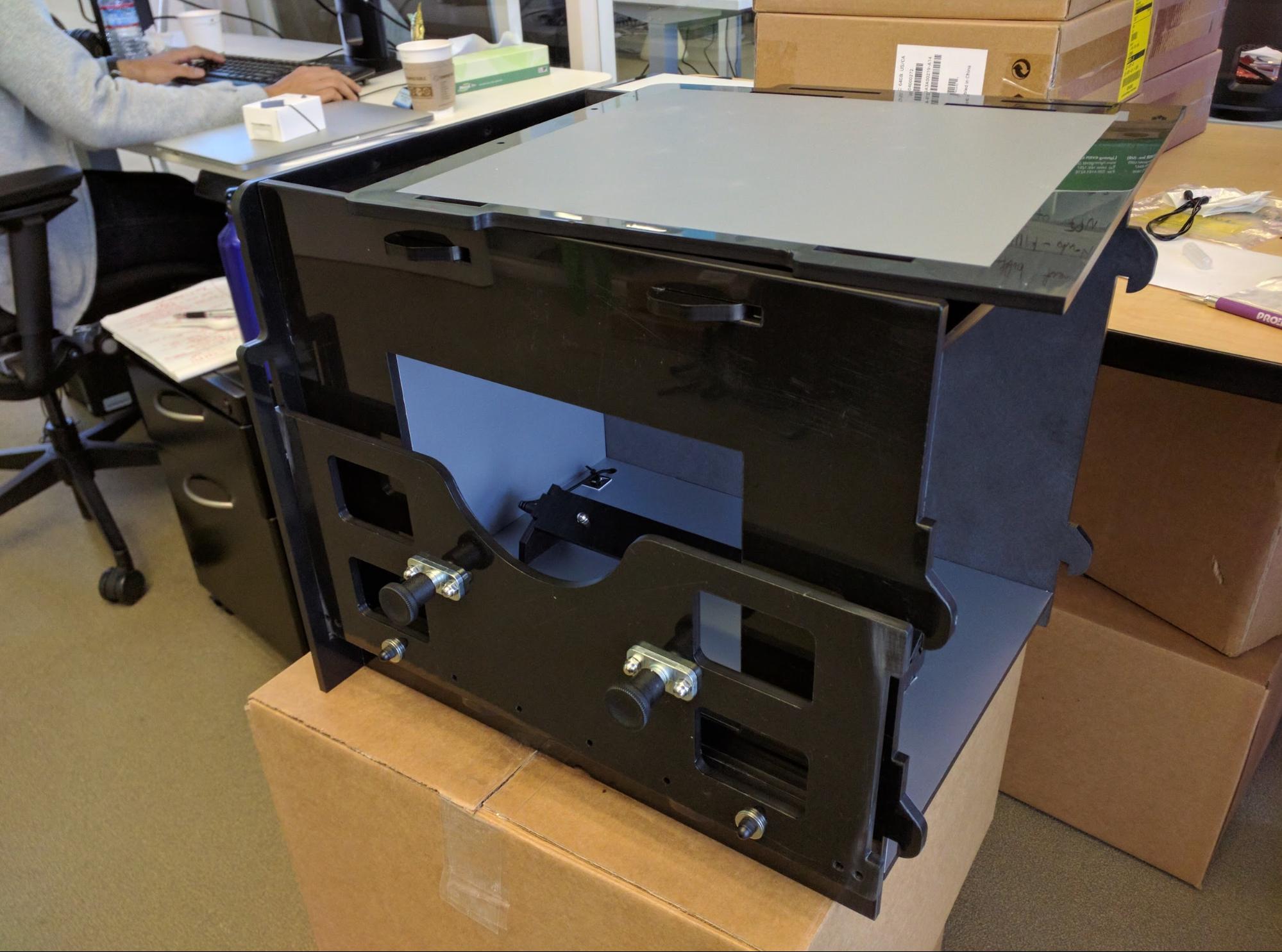
Figure 23. Right side, tablet holder inserted in slots (viewed
from back of box so it appears on the left).
If the tabs are too tight to allow the tablet holder to move up and down, sand
the tabs with 100 grit sandpaper to thin them and create a better fit.
- Snap the left panel into place by pushing and sliding it upwards, as shown
in figure 24:
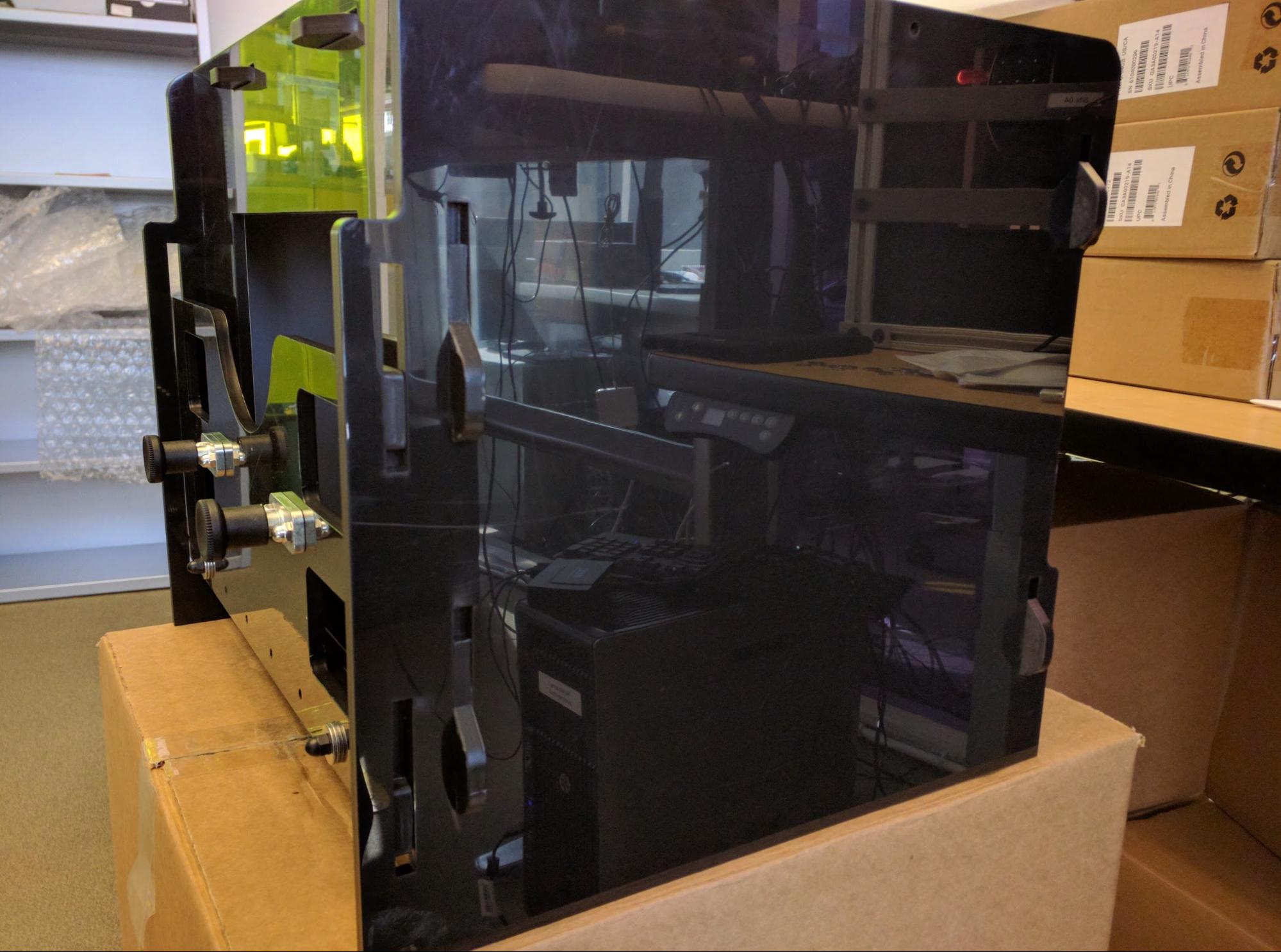
Figure 24. Left side panel in place.
- Gather the handle parts shown in Figure 25:
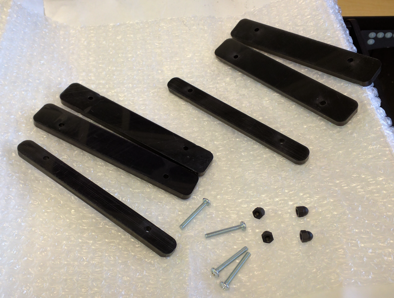
Figure 25. Handle and box lock parts.
Hardware includes four wide plastic pieces (for outside the box) and two narrow
pieces (for top of the box). Screw holes are not placed symmetrically on the
plastic strips.
- Assemble the handle as shown in figure 26:
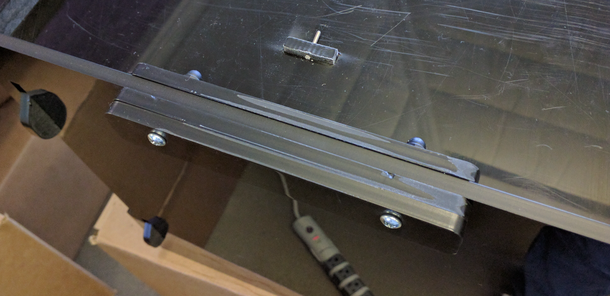
Figure 26. Assembled handle.
Acorn nuts are usually placed on the top of the box. While this is not strictly
necessary, it makes the outer part of the handle as flat as possible. If the
handle is loose, insert washers to allow the acorn nuts to tighten effectively.
Step 8: Final assembly
To perform final assembly of the ITS-in-a-box:
- Using two nylon screws (short or long), attach the square aperture panel
with phone mounts to the front of the box as shown in Figure 27:
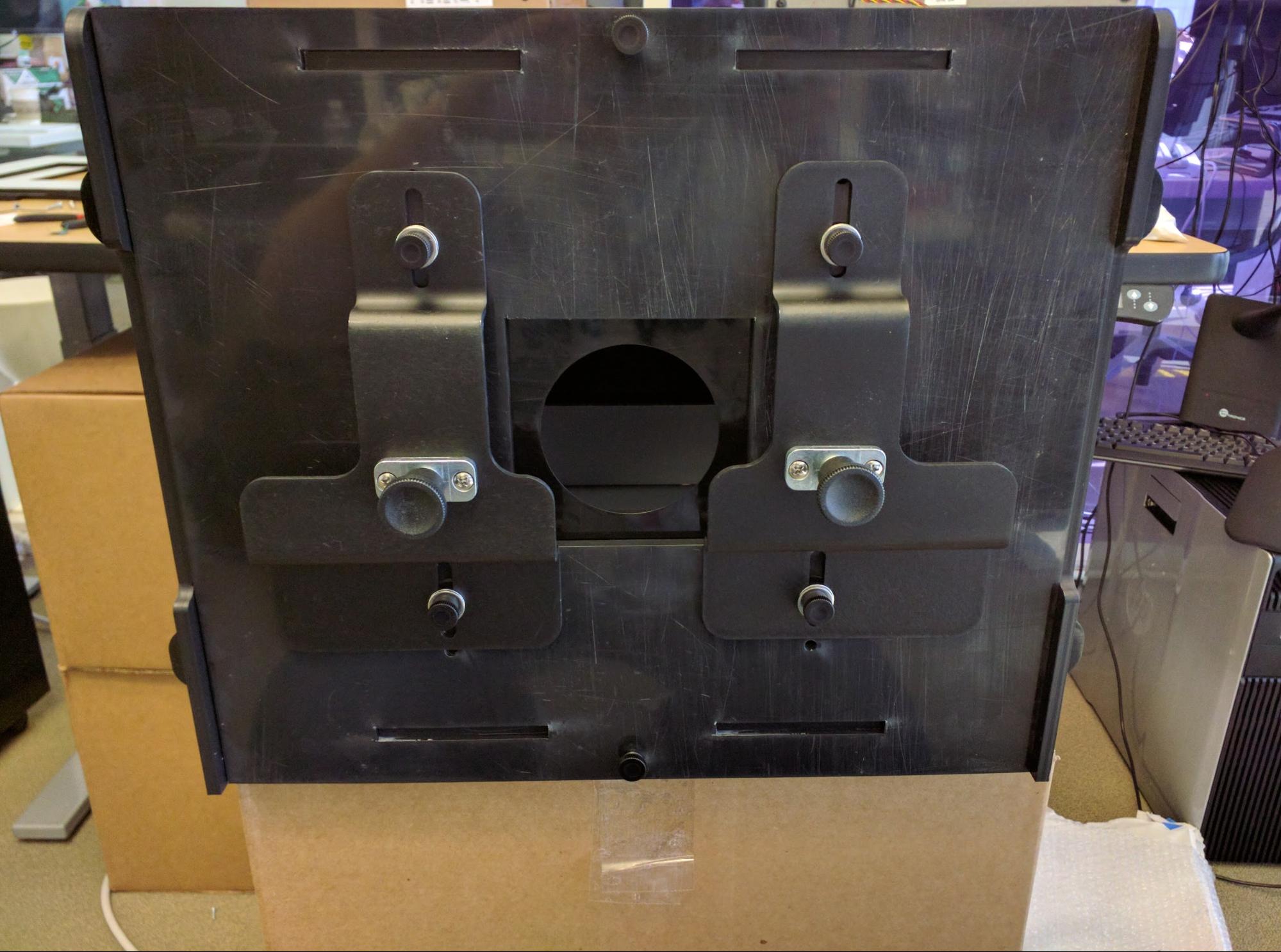
Figure 27. Attached front panel.
Place one screw on the top of the box and one screw on the bottom of the box.
- Test the 4"x4” gatorboard aperture blank to ensure it fits in the square
opening, as shown in Figure 28:
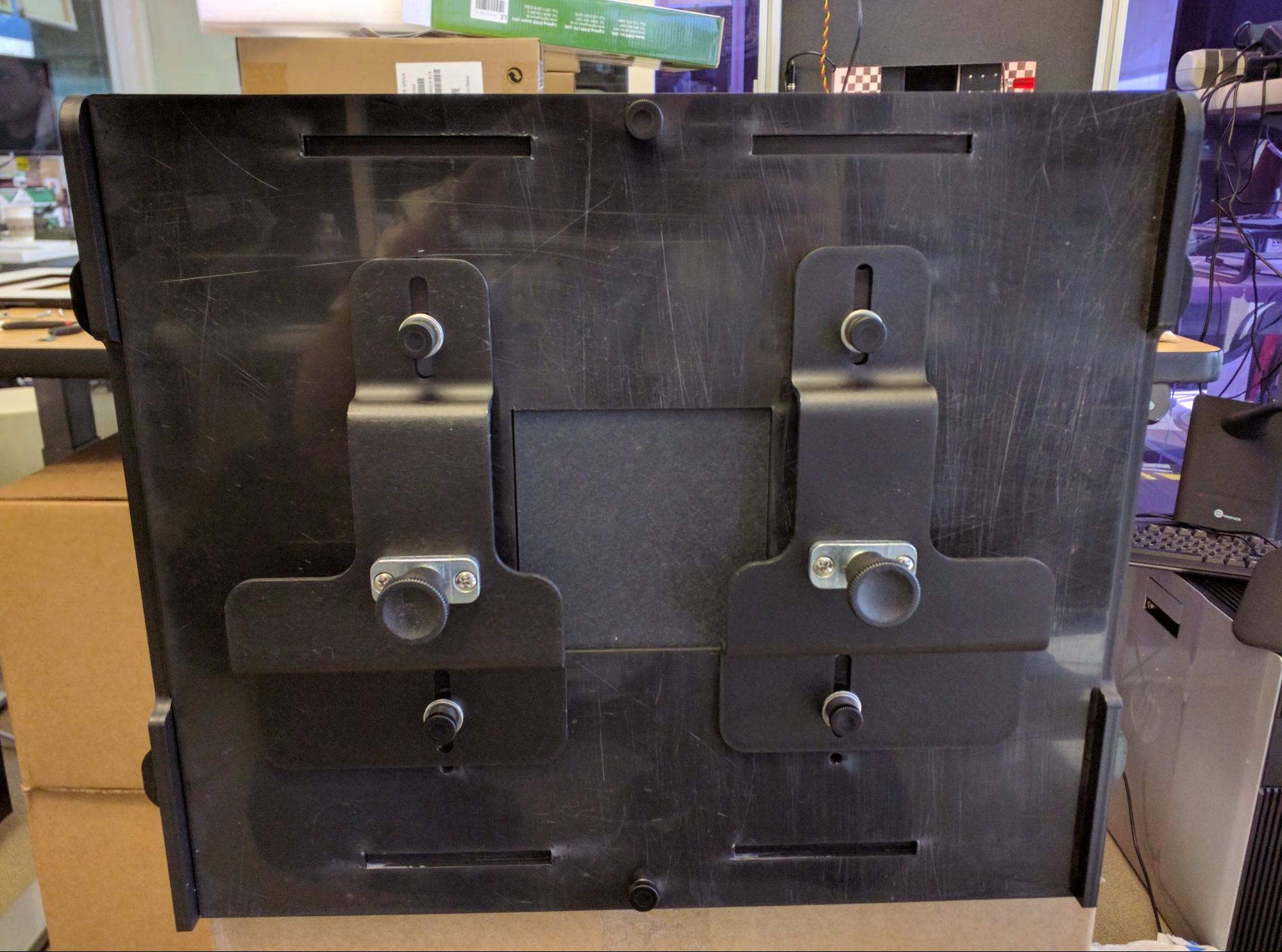
Figure 28. Gatorboard installed, no aperture cut.
The fit should be snug. If the blank is too tight, shave it; if too loose, make
another.
- Cut apertures for cameras. You can cut a single aperture (for testing a
single phone) or two apertures (for testing two phones). Apertures for the Pixel
and Pixel XL front and rear cameras are shown in Figure 29:
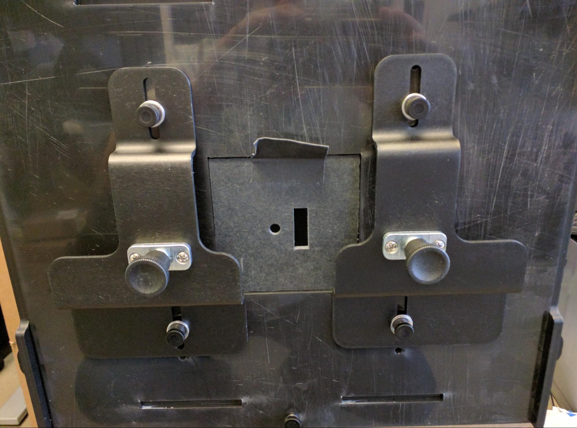
Figure 29. Front of ITS-in-a-box with front and rear camera
aperture cuts.
The front camera is a circular aperture since there is no flash or laser, while
the rear camera is a rectangular aperture that allows the flash and laser to
operate without being blocked.